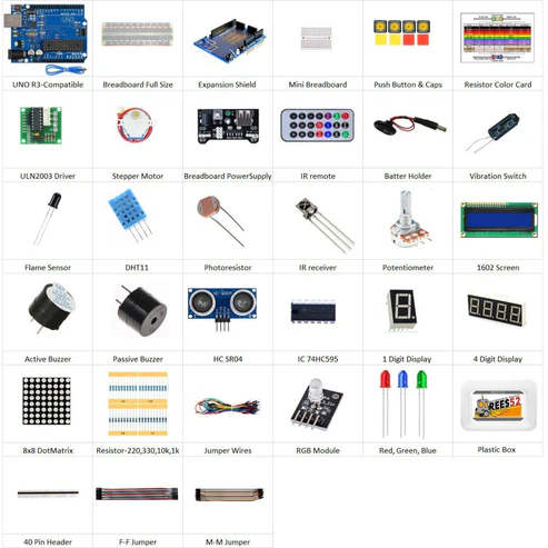
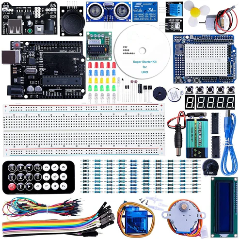
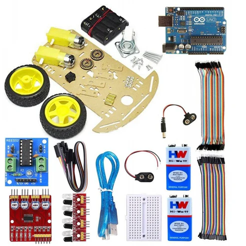
- Arduino uno with usb cable- 1
- Arduino Leonardo with USB cable- 1
- NRF24lo1 – 2
- Jumper wires MALE TO FEMALE – 40 piece
- 9v battery – 2
- Battery snapper with DC jack – 2
HARDWARE REQUIRED
- Arduino uno with usb cable- 1
- Arduino Leonardo – 1
- NRF24lo1 – 2
- Jumper wires MALE TO FEMALE – 40 piece
- Arduino cable – 1
- 9v battery – 2
- Battery snapper with DC jack – 2
NRF24L01 Module with ARDUINO LEONARDO
The Arduino Leonardo is a microcontroller board based on the ATmega32u4. It has 20 digital input/output pins (of which 7 can be used as PWM outputs and 12 as analog inputs), a 16 MHz crystal oscillator, a micro USB connection, a power jack, an ICSP header, and a reset button. It contains everything needed to support the microcontroller; simply connect it to a computer with a USB cable or power it with a AC-to-DC adapter or battery to get started.The Leonardo differs from all preceding boards in that the ATmega32u4 has built-in USB communication, eliminating the need for a secondary processor. This allows the Leonardo to appear to a connected computer as a mouse and keyboard, in addition to a virtual (CDC) serial / COM port.
PIN DESCRIPTION
Arduino Leonardo
- Microcontroller: ATmega32u4
- Operating Voltage: 5V
- Input Voltage (recommended): 7-12V
- Input Voltage (limits): 6-20V
- Digital I/O Pins: 20
- PWM Channels: 7
- Analog Input Channels: 12
- DC Current per I/O Pin: 40 mA
- DC Current for 3.3V Pin: 50 mA
- Flash Memory: 32 KB (ATmega32u4) of which 4 KB used by bootloader
- SRAM: 2.5 KB (ATmega32u4)
- EEPROM: 1 KB (ATmega32u4)
- Clock Speed: 16 MHz
NRF24L01 Module
- Voltage: 3-3.6V (recommended 3.3V) V
- Maximum output power: +20dBm
- Emission mode current(peak): 115mA
- Receive Mode Current(peak): 45mA
- Power-down mode current: 4.2uA
SOFTWARE REQUIRED
Arduino IDE ( programmable software for Arduino boards )
You can download the software from this link : https://www.arduino.cc/en/Main/Software

LIBRARY REQUIRED
To download the SPI library
Sketch –> Include Library –> SPI

IF it is pre downloaded otherwise click on manage libraries to download the libraries
PIN DIAGRAM
- NRF24L01 Module
CIRCUIT DESCRIPTION

CODE
Before uploading code select the appropriate board , here you choose Leonardo board .
NRF24L01 Module with ARDUINO UNO
SPECIFICATION
- Microcontroller– ATmega328
- Operating Voltage– 5V
- Input Voltage (recommended) – 7to12V
- Input Voltage(limit) – 6to20V
- Digital I/O Pins-14 (of which 6 provide PWM output)
- Analog Input Pins-6
- DC Current per I/O Pin-40 mA
- DC Current for 3.3V Pin-50 mA
- Flash Memory-32 KB (ATmega328) of which 0.5 KB used by boot loader
- SRAM-2 KB (ATmega328)
- EEPROM-1 KB (ATmega328)
- Clock Speed-16 MHz
CIRCUIT DESCRIPTION

CODE
Before uploading code select the appropriate board , here you choose UNO board .
WORKING
The nrf24lo1 is a trans receiver module. In this one nrf24lo1 is transmitting and other one is receiving the data. We see the
Data transmission in the serial monitor.


