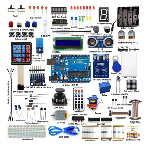
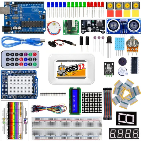
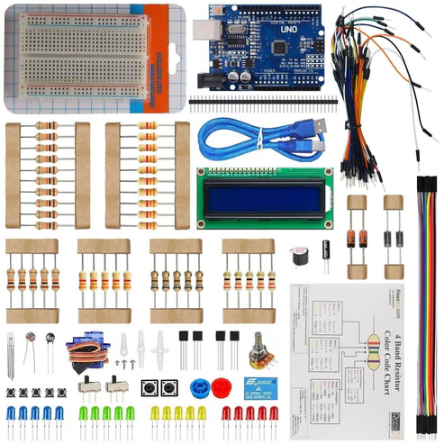
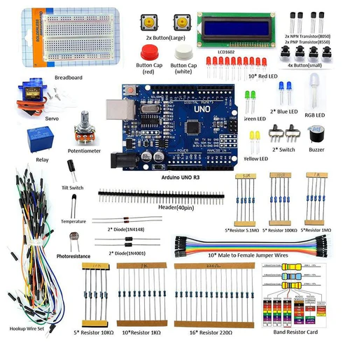
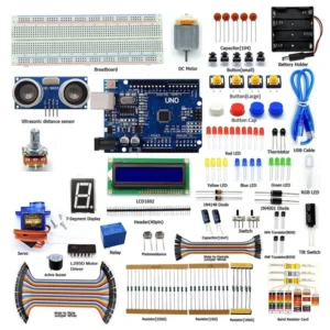
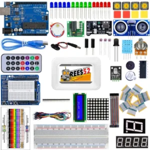
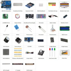
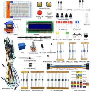
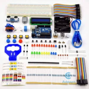
HARDWARE REQUIRED
SOFTWARE REQUIRED
Arduino IDE 1.8.5 (Programmable Platform for Arduino Boards)
Click to download the software: https://www.arduino.cc/en/Main/Software

PIN DESCRIPTION
HC SR04 ULTRASONIC SENSOR

16*2 LCD DISPLAY

10K POTENTIOMETER


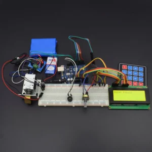
CIRCUIT DESCRIPTION


Connection for LCD 16*2 Display with Arduino uno
| LCD 16 * 2 |
Arduino |
| VSS |
GND |
| VCC |
5V |
| RS |
PIN 11 |
| R/W |
PIN 10 |
| E |
PIN 9 |
| DB4 |
PIN 2 |
| DB5 |
PIN 3 |
| DB6 |
PIN 4 |
| |
PIN 5 |
| LED+ (A) |
5V |
| LED- (K) |
GND |
Connection for HC SR-04 Ultrasonic Sensor with Arduino UNO
| Ultrasonic Sensor |
Arduino |
| VCC |
5V |
| GND |
GND |
| ECHO |
Pin 12 |
| TRIG |
Pin 13 |
Connection for the potentiometer with LCD 16*2 and Breadboard
| Potentiometer |
LCD |
Breadboard |
| Pin 1 (left) |
|
5v |
| Pin 2(mid) |
Pin 3 |
|
| Pin 3 (right) |
|
Gnd |
CODE
Before coding, you have to install new ping library
https://drive.google.com/open?id=11gy_6v61-Eq0sAz8RJF_sn5Tl0g7z8Cj
Sketch > Include library > Manage Library > Search NEWPING library > download it
Or you download NewPing Library from other site.
https://drive.google.com/open?id=107vaWoBXZ8t6xtLExf7GQPetTcTP6glO
/*
HC-SR04 Ultrasonic Sensor with LCD display
HC-SR04 Ultrasonic Sensor
VCC to Arduino 5V
GND to Arduino GND
Echo to Arduino pin 12
Trig to Arduino pin 13
LCD Display –
VSS to Arduino GND
VCC to Arduino 5V
VEE to Arduino GND
RS to Arduino pin 12
R/W to Arduino pin gnd
E to Arduino pin 11
DB4 to Arduino pin 10
DB5 to Arduino pin 9
DB6 to Arduino pin 8
DB7 to Arduino pin 7
LED+ to Arduino 5V
LED- to Arduino GND
*/
#include <LiquidCrystal.h> //Load Liquid Crystal Library
LiquidCrystal LCD(12, 11, 10, 9, 8, 7); //Create Liquid Crystal Object called LCD (rs=12 E=11 D4=10 D5=9 D6=8 D7=7)
//Assigning pins of Arduino board to some variable
#define trigPin 2 //Sensor Echo pin connected to Arduino pin 13
#define echoPin 3 //Sensor Trip pin connected to Arduino pin 12
/* The setup() function is called when a sketch starts. It is used to initialize variables, pin modes,
start using libraries, etc. This function will only run once,
after each power up or reset of the Arduino board. */
void setup(){
pinMode(trigPin, OUTPUT); // OUTPUT means the “trigPin” which is actually pin no 13 is directed to give output instruction form the arduino.
pinMode(echoPin, INPUT); // OUTPUT means the “echoPin” which is actually pin no 12 is directed to give output instruction form the arduino.
LCD.begin(16, 2); //Tell Arduino to start your 16 column 2 row LCD
LCD.setCursor(0, 0); //Set LCD cursor to upper left corner, column 0, row 0
LCD.print(“Target Distance:”); //Print Message on First Row
}
void loop() {
long duration, distance;
digitalWrite(trigPin, LOW); // digitalWrite is used to write a HIGH or a LOW value to a digital pin (LOW is the voltage level).
delayMicroseconds(2);
digitalWrite(trigPin, HIGH); // digitalWrite is used to write a HIGH or a LOW value to a digital pin (HIGH is the voltage level).
delayMicroseconds(10);
digitalWrite(trigPin, LOW); // digitalWrite is used to write a HIGH or a LOW value to a digital pin (LOW is the voltage level).
duration = pulseIn(echoPin, HIGH);
distance = (duration / 2) / 29.1;
LCD.setCursor(0, 1); //Set cursor to first column of second row
LCD.print(” “); //Print blanks to clear the row
LCD.setCursor(0, 1); //Set Cursor again to first column of second row
LCD.print(distance); //Print measured distance
LCD.print(” cm”); //Print your units.
delay(250); //pause to let things settle
}
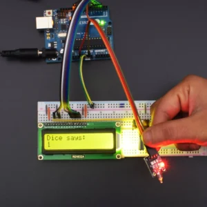
RUN SKETCH AND VERIFY OUTPUT
After compiling, uploading and running it
As far as the object goes far from the ultra-sonic sensor, Distance will be vary and measured distance will be show in LCD
in the Serial Monitor (Tools -> Serial Monitor or Ctrl + Shift + M) the sensor was sending correct data
Note: Must Set the baud Rate to 115200
Ping: 36 cm or the value shown in the serial monitor depends on the object distance from the ultra-sonic sensor.