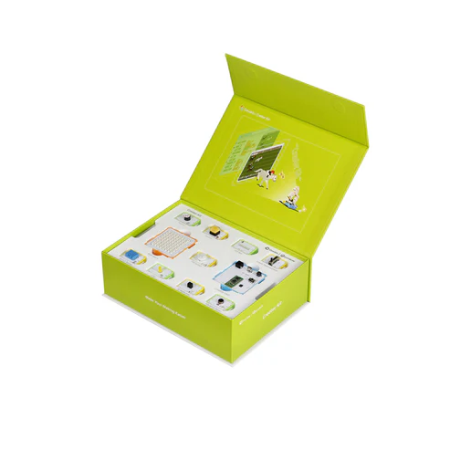
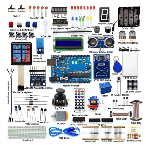
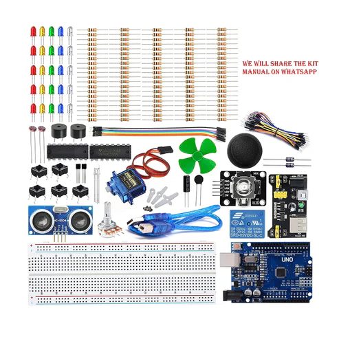
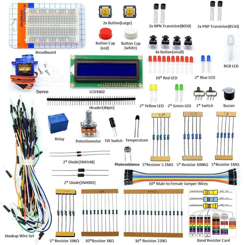
KIT INCLUDES:
HARDWARE REQUIRED
KIT INCLUDES:
SOFTWARE REQUIRED
Arduino IDE 1.8.5 (programmable platform for Arduino)
Click To Download :https://www.arduino.cc/en/Main/Software


SPECIFICATIONS
KNOCK SENSOR MODULE
The knock sensor module detects a knock or tap. If the knock is hard enough, the sensor switch will briefly close, allowing the knock to be detected by a circuit or device such as an Arduino. A built in 10k resistor on the module can be used as a pull-up or pull-down resistor.
2 COLOUR LED MODULE
| Operating Voltage |
2.0v ~ 2.5v |
| Using Current |
10mA |
| Diameter |
3mm |
| Package Type |
Diffusion |
| Color |
Red + Green |
| Beam Angle |
150 |
| Wavelength |
571nm + 644nm |
| Luminosity Intensity (MCD) |
20-40; 40-80 |

PIN DESCRIPTION
KNOCK SENSOR MODULE


2 COLOUR LED MODULE


CIRCUIT DESCRIPTION

- Connect buzzer’s GND to Arduino’s GND Pin.
- Connect buzzer’s positive terminal to arduino’s Digital Pin 7.
- Connect the Signal Pin of Knock sensor with arduino Digital Pin 4 of Arduino uno.
- Connect Positive terminal of Knock sensor with arduino 5v and GND of Knock sensor to GND pin of arduino uno.
- Connect 2 colour Led Module with arduino uno. The first pin of module connects with Digital Pin 5 of arduino and second pin of module connects with Digital Pin 6 of Arduino. And the last pin of module connects to GND of Arduino.
- Last step is to upload the code to arduino uno.
CODE
Click to see code here: https://docs.google.com/document/d/e/2PACX-1vThUb5AVAmXL4DMrhlUWVgXRlhG603wXARfzy7BpzA9_s-PoPrMl4qW3SfGYQAeuHyd5Y4m0thNyAu0/pub
// This is a example of what you can do with the shock sensor.
int ShockSensor = 4; // Pin assigned for Sensor
int RedLed = 5; // Pin assigned for Red LED
int GreenLed = 6; // Pin assigned for Green LED
int Buzzer = 7; // Pin assigned for Buzzer
int value = HIGH;
boolean Alarm = false; // Set default value as false
unsigned long LatestKnockTime;
int TriggerTime = 25; // You can change this if you want the alarm to trigger longer.
/* The setup() function is called when a sketch starts. It is used to initialize variables, pin modes, start using libraries, etc. This function will only run once, after each power up or reset of the Arduino board. */
void setup ()
{
Serial.begin(9600); // Baud Rate
pinMode (ShockSensor, INPUT) ; // the sensor set to input
pinMode (Buzzer, OUTPUT); // Set Buzzer as Output
pinMode (RedLed, OUTPUT); // Set LED as Output
pinMode (GreenLed, OUTPUT); // Set LED as Output
}
/* The loop() function executes the program repeatedly until Specified. */
void loop ()
{
value = digitalRead (ShockSensor) ; // Reading value
if (value == LOW)
{
LatestKnockTime = millis();
if (!Alarm)
{
Serial.println(“Shock detected”); // You can add a LCD and make it print on LCD
digitalWrite (GreenLed, HIGH);
digitalWrite (Buzzer, HIGH);
delay(1000);
digitalWrite (Buzzer, LOW);
delay(1000);
digitalWrite (Buzzer, HIGH);
delay(1000);
digitalWrite (Buzzer, LOW);
delay(1000);
digitalWrite (Buzzer, HIGH);
delay(1000);
digitalWrite (Buzzer, LOW);
delay(1000);
digitalWrite (Buzzer, HIGH);
delay(1000);
digitalWrite (Buzzer, LOW);
delay(1000);
Alarm = false;
}
}
else
{
if( (millis()–LatestKnockTime) > TriggerTime && Alarm)
{
Serial.println(“Nothing Detected”); // Print the Message
digitalWrite (Buzzer, LOW); // Buzzer is inactive
Alarm = false;
}
}
}
WORKING
Welcome to the Arduino Based Project Electronic Mail Notifier which consists of Knock Sensor and 2 color LED Module. This module consist of a common cathode 3mm red/green LED and a 0Ω resistor, Since operating voltage is 2.0v ~2.5v you may need to use limiting resistors to prevent burnout when connecting to the Arduino. Here we design an circuit which used as an electronic letter box notifier if postman drop a letter in box alarm activated after removing letter reset the alarm.
This module is a knock sensor. When you knock it, it can send a momentary signal. We can combine it with Arduino to make some interesting experiment, e.g. electronic drum.
.gif)