In this project, we have used the 2.8inch TFT screen to display the heart rate graph of a person as measured by the heart rate sensor.
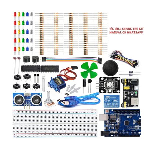
This 2.4” TFT Touchscreen is designed to suitable for Arduino UNO/Mega2560. It can directly plug into the UNO/Mega2560 board without any wiring and soldering. Library is compatible with Adafruit TFT touchscreen shield, which is easy to use.
(SDK pin is the pin after the pin 13 and SCL pin is next to it).
int x1=90;
int y1=0;
int x2=0;
int y2=0;
#include <Adafruit_GFX.h> // Core graphics library
#include <Adafruit_TFTLCD.h> // Hardware-specific library
// The control pins for the LCD can be assigned to any digital or
// analog pins…but we’ll use the analog pins as this allows us to
// double up the pins with the touch screen (see the TFT paint example).
#define LCD_CS A3 // Chip Select goes to Analog 3
#define LCD_CD A2 // Command/Data goes to Analog 2
#define LCD_WR A1 // LCD Write goes to Analog 1
#define LCD_RD A0 // LCD Read goes to Analog 0
#define LCD_RESET A4 // Can alternately just connect to Arduino’s reset pin
// When using the BREAKOUT BOARD only, use these 8 data lines to the LCD:
// For the Arduino Uno, Duemilanove, Diecimila, etc.:
// D0 connects to digital pin 8 (Notice these are
// D1 connects to digital pin 9 NOT in order!)
// D2 connects to digital pin 2
// D3 connects to digital pin 3
// D4 connects to digital pin 4
// D5 connects to digital pin 5
// D6 connects to digital pin 6
// D7 connects to digital pin 7
// For the Arduino Mega, use digital pins 22 through 29
// (on the 2-row header at the end of the board).
// Assign human-readable names to some common 16-bit color values:
#define BLACK 0x0000
#define BLUE 0x001F
#define RED 0xF800
#define GREEN 0x07E0
#define CYAN 0x07FF
#define MAGENTA 0xF81F
#define YELLOW 0xFFE0
#define WHITE 0xFFFF
Adafruit_TFTLCD tft(LCD_CS, LCD_CD, LCD_WR, LCD_RD, LCD_RESET);
// If using the shield, all control and data lines are fixed, and
// a simpler declaration can optionally be used:
// Adafruit_TFTLCD tft;
//code copied from arduino.cc
int pulsePin = SCL; // Pulse Sensor purple wire connected to analog pin A0
int blinkPin = 13; // pin to blink led at each beat
// Volatile Variables, used in the interrupt service routine!
volatile int BPM; // int that holds raw Analog in 0. updated every 2mS
volatile int Signal; // holds the incoming raw data
volatile int IBI = 600; // int that holds the time interval between beats! Must be seeded!
volatile boolean Pulse = false; // “True” when User’s live heartbeat is detected. “False” when not a “live beat”.
volatile boolean QS = false; // becomes true when Arduoino finds a beat.
static boolean serialVisual = true; // Set to ‘false’ by Default. Re-set to ‘true’ to see Arduino Serial Monitor ASCII Visual Pulse
volatile int rate[10]; // array to hold last ten IBI values
volatile unsigned long sampleCounter = 0; // used to determine pulse timing
volatile unsigned long lastBeatTime = 0; // used to find IBI
volatile int P = 512; // used to find peak in pulse wave, seeded
volatile int T = 512; // used to find trough in pulse wave, seeded
volatile int thresh = 525; // used to find instant moment of heart beat, seeded
volatile int amp = 100; // used to hold amplitude of pulse waveform, seeded
volatile boolean firstBeat = true; // used to seed rate array so we startup with reasonable BPM
volatile boolean secondBeat = false; // used to seed rate array so we startup with reasonable BPM
void setup()
{
pinMode(blinkPin,OUTPUT); // pin that will blink to your heartbeat!
Serial.begin(115200); // we agree to talk fast!
interruptSetup(); // sets up to read Pulse Sensor signal every 2mS
#ifdef USE_ADAFRUIT_SHIELD_PINOUT
Serial.println(F(“Using Adafruit 2.8\” TFT Arduino Shield Pinout”));
#else
Serial.println(F(“Using Adafruit 2.8\” TFT Breakout Board Pinout”));
#endif
Serial.print(“TFT size is “); Serial.print(tft.width()); Serial.print(“x”); Serial.println(tft.height());
tft.reset();
uint16_t identifier = tft.readID();
if(identifier == 0x9325) {
Serial.println(F(“Found ILI9325 LCD driver”));
} else if(identifier == 0x9328) {
Serial.println(F(“Found ILI9328 LCD driver”));
} else if(identifier == 0x7575) {
Serial.println(F(“Found HX8347G LCD driver”));
} else if(identifier == 0x9341) {
Serial.println(F(“Found ILI9341 LCD driver”));
} else if(identifier == 0x8357) {
Serial.println(F(“Found HX8357D LCD driver”));
} else {
Serial.print(F(“Unknown LCD driver chip: “));
Serial.println(identifier, HEX);
Serial.println(F(“If using the Adafruit 2.8\” TFT Arduino shield, the line:”));
Serial.println(F(” #define USE_ADAFRUIT_SHIELD_PINOUT”));
Serial.println(F(“should appear in the library header (Adafruit_TFT.h).”));
Serial.println(F(“If using the breakout board, it should NOT be #defined!”));
Serial.println(F(“Also if using the breakout, double-check that all wiring”));
Serial.println(F(“matches the tutorial.”));
return;
}
tft.begin(identifier); // UN-COMMENT THE NEXT LINE AND APPLY THAT VOLTAGE TO THE A-REF PIN
tft.fillScreen(BLACK);
// IF YOU ARE POWERING The Pulse Sensor AT VOLTAGE LESS THAN THE BOARD VOLTAGE,
// analogReference(EXTERNAL);
}
// Where the Magic Happens
void loop()
{
serialOutput();
if (QS == true) // A Heartbeat Was Found
{
// BPM and IBI have been Determined
// Quantified Self “QS” true when arduino finds a heartbeat
serialOutputWhenBeatHappens(); // A Beat Happened, Output that to serial.
QS = false; // reset the Quantified Self flag for next time
}
delay(20); // take a break
}
void interruptSetup()
{
// Initializes Timer2 to throw an interrupt every 2mS.
TCCR2A = 0x02; // DISABLE PWM ON DIGITAL PINS 3 AND 11, AND GO INTO CTC MODE
TCCR2B = 0x06; // DON’T FORCE COMPARE, 256 PRESCALER
OCR2A = 0X7C; // SET THE TOP OF THE COUNT TO 124 FOR 500Hz SAMPLE RATE
TIMSK2 = 0x02; // ENABLE INTERRUPT ON MATCH BETWEEN TIMER2 AND OCR2A
sei(); // MAKE SURE GLOBAL INTERRUPTS ARE ENABLED
}
void serialOutput()
{ // Decide How To Output Serial.
if (serialVisual == true)
{
arduinoSerialMonitorVisual(‘-‘, Signal); // goes to function that makes Serial Monitor Visualizer
}
else
{
sendDataToSerial(‘S’, Signal); // goes to sendDataToSerial function
}
}
void serialOutputWhenBeatHappens()
{
if (serialVisual == true) // Code to Make the Serial Monitor Visualizer Work
{
Serial.print(” Heart-Beat Found “); //ASCII Art Madness
Serial.print(“BPM: “);
Serial.println(BPM);
int t=millis()/1000;
tft.fillRect(150,200,240,320,BLACK);
tft.setRotation(2); //converting time to seconds
x2=map(BPM,0,220,90,240); Serial.println(x2);
y2=map(t,0,120,0,320); Serial.println(y2);
tft.drawLine(x1,y1,x2,y2,WHITE);
x1=x2; y1=y2;
tft.setCursor(150,200);
tft.setTextSize(3);
tft.setTextColor(WHITE);
tft.setRotation(3);
tft.print(BPM);
tft.print(” BPM”);
}
else
{
sendDataToSerial(‘B’,BPM); // send heart rate with a ‘B’ prefix
sendDataToSerial(‘Q’,IBI); // send time between beats with a ‘Q’ prefix
}
}
void arduinoSerialMonitorVisual(char symbol, int data )
{
const int sensorMin = 0; // sensor minimum, discovered through experiment
const int sensorMax = 1024; // sensor maximum, discovered through experiment
int sensorReading = data; // map the sensor range to a range of 12 options:
int range = map(sensorReading, sensorMin, sensorMax, 0, 11);
// do something different depending on the
// range value:
}
void sendDataToSerial(char symbol, int data )
{
Serial.print(symbol);
Serial.println(data);
}
ISR(TIMER2_COMPA_vect) //triggered when Timer2 counts to 124
{
cli(); // disable interrupts while we do this
Signal = analogRead(pulsePin); // read the Pulse Sensor
sampleCounter += 2; // keep track of the time in mS with this variable
int N = sampleCounter – lastBeatTime; // monitor the time since the last beat to avoid noise
// find the peak and trough of the pulse wave
if(Signal < thresh && N > (IBI/5)*3) // avoid dichrotic noise by waiting 3/5 of last IBI
{
if (Signal < T) // T is the trough
{
T = Signal; // keep track of lowest point in pulse wave
}
}
if(Signal > thresh && Signal > P)
{ // thresh condition helps avoid noise
P = Signal; // P is the peak
} // keep track of highest point in pulse wave
// NOW IT’S TIME TO LOOK FOR THE HEART BEAT
// signal surges up in value every time there is a pulse
if (N > 250)
{ // avoid high frequency noise
if ( (Signal > thresh) && (Pulse == false) && (N > (IBI/5)*3) )
{
Pulse = true; // set the Pulse flag when we think there is a pulse
digitalWrite(blinkPin,HIGH); // turn on pin 13 LED
IBI = sampleCounter – lastBeatTime; // measure time between beats in mS
lastBeatTime = sampleCounter; // keep track of time for next pulse
if(secondBeat)
{ // if this is the second beat, if secondBeat == TRUE
secondBeat = false; // clear secondBeat flag
for(int i=0; i<=9; i++) // seed the running total to get a realisitic BPM at startup
{
rate[i] = IBI;
}
}
if(firstBeat) // if it’s the first time we found a beat, if firstBeat == TRUE
{
firstBeat = false; // clear firstBeat flag
secondBeat = true; // set the second beat flag
sei(); // enable interrupts again
return; // IBI value is unreliable so discard it
}
// keep a running total of the last 10 IBI values
word runningTotal = 0; // clear the runningTotal variable
for(int i=0; i<=8; i++)
{ // shift data in the rate array
rate[i] = rate[i+1]; // and drop the oldest IBI value
runningTotal += rate[i]; // add up the 9 oldest IBI values
}
rate[9] = IBI; // add the latest IBI to the rate array
runningTotal += rate[9]; // add the latest IBI to runningTotal
runningTotal /= 10; // average the last 10 IBI values
BPM = 60000/runningTotal; // how many beats can fit into a minute? that’s BPM!
QS = true; // set Quantified Self flag
// QS FLAG IS NOT CLEARED INSIDE THIS ISR
}
}
if (Signal < thresh && Pulse == true)
{ // when the values are going down, the beat is over
digitalWrite(blinkPin,LOW); // turn off pin 13 LED
Pulse = false; // reset the Pulse flag so we can do it again
amp = P – T; // get amplitude of the pulse wave
thresh = amp/2 + T; // set thresh at 50% of the amplitude
P = thresh; // reset these for next time
T = thresh;
}
if (N > 2500)
{ // if 2.5 seconds go by without a beat
thresh = 512; // set thresh default
P = 512; // set P default
T = 512; // set T default
lastBeatTime = sampleCounter; // bring the lastBeatTime up to date
firstBeat = true; // set these to avoid noise
secondBeat = false; // when we get the heartbeat back
}
sei(); // enable interrupts when youre done!
}// end isr
Welcome to the Arduino Based project which consists of heart rate sensor module that gives an analog output which is converted into beats per minute in the code and the resultant graph of the bpm is displayed on the TFT screen.
The heart rate is monitored every second.