In this project, we will build a Digital Protractor using MPU6050 and Arduino. Here a servo motor is used to display the angle on a protractor image. The Servo motor shaft will rotate on a protractor image to indicate the angle which is also displayed on a 16xLCD display.
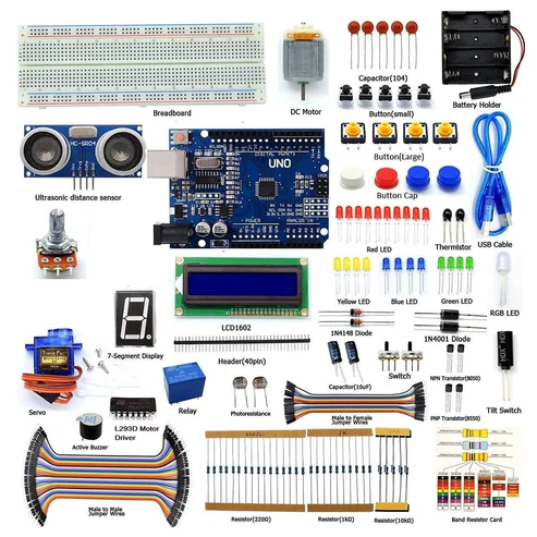
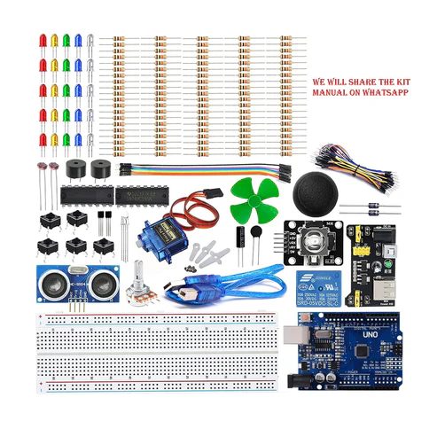
HARDWARE REQUIRED
- Arduino Uno with USB cable-1
- MPU6050 Gyroscope Module – 1
- 16X2 LCD Display -1
- SG90-Servo Motor -1
- Jumper wires (Male to Male & Male to Female) – 40 pcs each
- 10K Potentiometer – 1
- 830 Pt. breadboard – 1
- 170 pt. breadboard – 1
- Single Stand wire 1mt – 1
SOFTWARE REQUIRED
Arduino IDE 1.8.5 (programmable platform for Arduino)
Click To Download: https://www.arduino.cc/en/Main/Software
LIBRARY REQUIRED
Servo
https://drive.google.com/open?id=1XEyFZik_ENYtE4LOf3mOP3kqfqH3FNh2
LCD 16*2 Display
https://drive.google.com/open?id=14CpOZPTgmPcHedB1oDqeTVFI4eMwMcf7
Wire
https://drive.google.com/open?id=1Ej-R75OikJAlHrj275zYvKNzDN3cm0zi
MPU6050
https://drive.google.com/open?id=1LiY4DTqVo6vXTd-re3vsjldu3bjaU3Wd
After downloading these libraries
To install the libraries – Go to sketch -> Include library -> add .zip library
CIRCUIT CONNECTION
Circuit Connections between Arduino UNO and MPU6050:
| MPU6050 |
Arduino UNO |
| VCC |
+5V |
| GND |
GND |
| SCL |
A5 |
| SDA |
A4 |
Circuit Connections between Arduino UNO and Servo Motor:
| Servo Motor |
Arduino UNO |
| RED (VCC) |
+5V |
| ORANGE (PWM) |
9 |
| BROWN (GND) |
GND |
Circuit Connections between Arduino UNO and 16×2 LCD:
| LCD |
Arduino UNO |
| VSS |
GND |
| VDD |
+5V |
| V0 |
To Potentiometer Centre PIN
For Controlling the Contrast of the LCD |
| RS |
12 |
| RW |
GND |
| E |
11 |
| D4 |
7 |
| D5 |
6 |
| D6 |
5 |
| D7 |
4 |
| A |
+5V |
| K |
GND |
CODE
https://drive.google.com/open?id=1rsXReWi1u4AvQrBOCYIx7KVrEVSHnIOC
#include <Servo.h> //Include Servo Motor library for using Servo
#include <LiquidCrystal.h> //Include LCD library for using LCD
#include <Wire.h> //Include WIre library for using I2C
#include <MPU6050.h>
LiquidCrystal lcd(12,11,7,6,5,4); //Define LCD display pins RS,E,D4,D5,D6,D7
const int MPU_addr=0x68; //I2C MPU6050 Address
Servo myservo; //myservo object for class servo
int16_t axis_X,axis_Y,axis_Z;
int minVal=265;
int maxVal=402;
double x;
double y;
double z;
int pos = 0;
void setup()
{
Wire.begin(); //Begins I2C communication
Wire.beginTransmission(MPU_addr); //Begins Transmission with MPU6050
Wire.write(0x6B); //Puts MPU6050 in Sleep Mode
Wire.write(0); //Puts MPU6050 in power mode
Wire.endTransmission(true); //Ends Trasmission
myservo.attach(9); //Servo PWM pin as 9 in UNO
lcd.begin(16,2); //Sets LCD in 16X2 Mode
lcd.print(“REES52”);
delay(1000);
lcd.clear();
lcd.setCursor(0,0);
lcd.print(“Arduino”);
lcd.setCursor(0,1);
lcd.print(“MPU6050”);
delay(2000);
lcd.clear();
}
void loop()
{
Wire.beginTransmission(MPU_addr); //Begins I2C transmission
Wire.write(0x3B); //Start with register 0x3B (ACCEL_XOUT_H)
Wire.endTransmission(false);
Wire.requestFrom(MPU_addr,14,true); //Request 14 Registers from MPU6050
axis_X=Wire.read()<<8|Wire.read(); //Obtain 0x3B (ACCEL_XOUT_H) & 0x3C (ACCEL_XOUT_L)
axis_Y=Wire.read()<<8|Wire.read(); //0x3B (ACCEL_YOUT_H) & 0x3C (ACCEL_YOUT_L)
axis_Z=Wire.read()<<8|Wire.read(); //0x3B (ACCEL_ZOUT_H) & 0x3C (ACCEL_ZOUT_L)
int xAng = map(axis_X,minVal,maxVal,-90,90);
int yAng = map(axis_Y,minVal,maxVal,-90,90);
int zAng = map(axis_Z,minVal,maxVal,-90,90);
x= RAD_TO_DEG * (atan2(-yAng, -zAng)+PI); //Formula to calculate x values in degree
int pos = map(x,0,180,0,180); // As X value is from 0 to 360 deg
myservo.write(pos); // Write angle obtained 0 to 180 to servo
lcd.setCursor(0,0);
lcd.print(“Angle”);
lcd.setCursor(0,1);
lcd.print(x);
delay(500);
lcd.clear();
}
WORKING AND OUTPUT
Welcome to the Arduino-based project in which we are Making a digital protractor using the servo Motor and MPU6050 Accelerometer module. In the code Formula to calculate the x value in degrees (0 to 360) is given below. Here we convert only x because the servo motor rotation is based on x value movement.
x= RAD_TO_DEG * (atan2(-yAng, -zAng)+PI);
write the angle value to rotate the servo on the protractor image and Print those values on the 16×2 LCD. So, this is how MPU6050 with Arduino can be used to measure the angle.
Here servo motor is connected with Arduino and its shaft is projected on the protractor image indicating the angle of the inclined MPU6050
According to the orientation of the MPU 6050 module, we will see the inclination angle on the LCD as well servo motor along with a protractor image.
Try to move at different angles and check the degree rotation on LCD and Protractor.