6
My Cart₹7,521.32 (incl. tax)


![]()
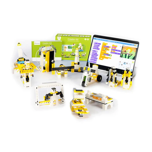
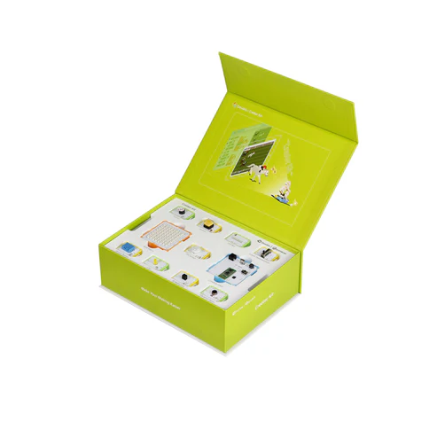
Robotics Kits and Electronics Component Store
Address: RobosuperSun Private Limited, Divine Hive Space 2.0 Business Centre, Office No-223, 2nd Floor, Whitefield’s Road Kondapur Telangana 500084.
Call: +91- 7396372530
Whatsapp: +91-7396372530
Email: roboclub@robokreeda.com