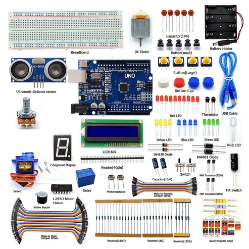
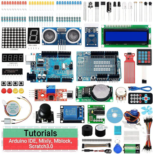
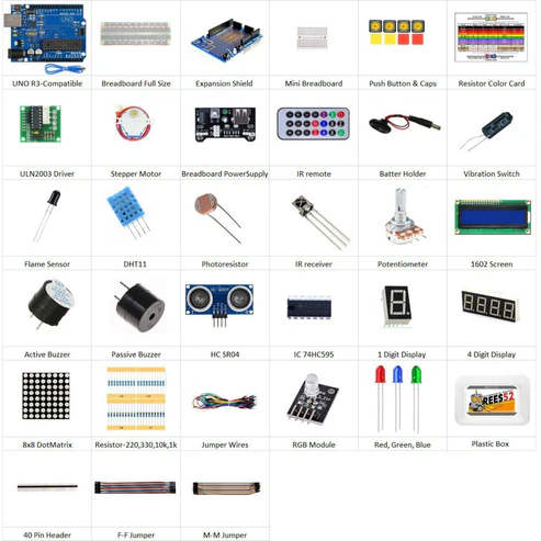
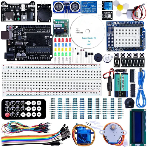
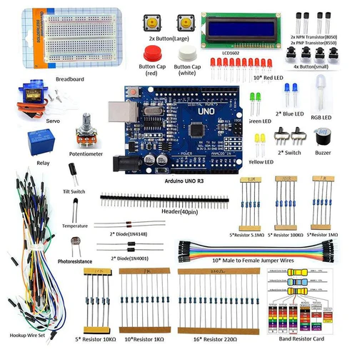
KIT INCLUDED:
HARDWARE REQUIRED
SOFTWARE REQUIRED
Arduino IDE 1.8.5 (programmable platform for Arduino)
Click To Download :https://www.arduino.cc/en/Main/Software


SPECIFICATIONS
GY-521 3-AXIS ACCELERATION GYROSCOPE MODULE
- Accelerometer ranges: ±2, ±4, ±8, ±16g
- Gyroscope ranges: ± 250, 500, 1000, 2000 °/s
- Voltage range: 3.3V – 5V (the module include a low drop-out voltage regulator)
This simple module contains everything required to interface to the Arduino and other controllers via I2C (use the Wire Arduino library) and give motion sensing information for 3 axes – X, Y and Z.
PIN DESCRIPTION
GY-521 3-AXIS ACCELERATION GYROSCOPE MODULE

With this module, you can measure:
- acceleration (= speed of movements) in three directions x, y, z;
- a rotation or an angles (in three directions);
- orientation
- VCC (The breakout board has a voltage regulator. Therefore, you can connect the board to 3.3V and 5V sources.)
- GND
- SCL (Serial Clock Line of the I2C protocol.)
- SDA (Serial Data Line of the I2C protocol.)
- XDA (Auxiliary data => I2C master serial data for connecting the module to external sensors.)
- XCL (Auxiliary clock => I2C master serial clock for connecting the module to external sensors.)
- AD0 (If this pin is LOW, the I2C address of the board will be 0x68. Otherwise, if the pin is HIGH, the address will be 0x69.)
- INT (Interrupt digital output)
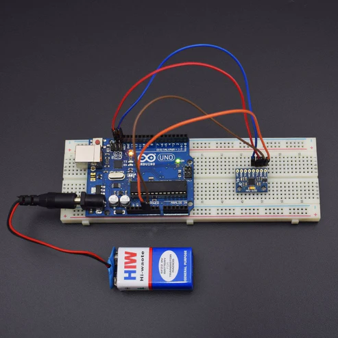
CIRCUIT CONNECTION
The accelerometer measures the acceleration along one direction, while the gyroscope measures the angular acceleration on one axis.
Connections:
- VCC -> 3.3 V / 5 V (better)
- GND -> GND
- SCL -> A5
- SDA -> A4
- XDA -> NC
- XCL -> NC
- ADO -> NC
- INT -> NC

LIBRARIES REQUIRED
Click to download https://drive.google.com/open?id=1V2hVX9eyigevA7h-loAFQ7-FQQ1EaFFP
Or you can install it from IDE
Sketch -> Include Library -> Manage Library -> Search for Wire


https://drive.google.com/open?id=1s7HN8meiyiXsmQlC9P-Sj97hO21Nk8jh
Or you can install it from IDE
Sketch -> Include Library -> Manage Library -> Search for MPU6050
CODE
Click to see the code:
https://drive.google.com/open?id=1TejkQKfUZGZMpTocmAMuy5Jk5KXFSOf2aYPkEIYZkUY
#include<Wire.h> // Library to communicate with I2C / TWI devices
const int MPU=0x68;
int16_t AcX,AcY,AcZ,Tmp,GyX,GyY,GyZ;
/* The setup() function is called when a sketch starts. It is used to initialize variables, pin modes, start using libraries, etc. This function will only run once, after each power up or reset of the Arduino board. */
void setup()
{
Wire.begin();
Wire.beginTransmission(MPU);
Wire.write(0x6B);
Wire.write(0);
Wire.endTransmission(true);
Serial.begin(9600); // Baud Rate
}
/* This Particular Function is used for Repeated Execution of the Circuit until Specified. */
void loop()
{
Wire.beginTransmission(MPU);
Wire.write(0x3B);
Wire.endTransmission(false);
Wire.requestFrom(MPU,12,true);
AcX=Wire.read()<<8|Wire.read(); // Read accelerometer values
AcY=Wire.read()<<8|Wire.read(); // Read accelerometer values
AcZ=Wire.read()<<8|Wire.read(); // Read accelerometer values
GyX=Wire.read()<<8|Wire.read(); // Read Gyroscope values
GyY=Wire.read()<<8|Wire.read(); // Read Gyroscope values
GyZ=Wire.read()<<8|Wire.read(); // Read Gyroscope values
Serial.print(“Accelerometer: “); // Print the Message
Serial.print(“X = “); Serial.print(AcX); // Print the values of accelerometer
Serial.print(” | Y = “); Serial.print(AcY); // Print the values of accelerometer
Serial.print(” | Z = “); Serial.println(AcZ); // Print the values of accelerometer
Serial.print(“Gyroscope: “); // Print the Message
Serial.print(“X = “); Serial.print(GyX); // Print the values of Gyroscope
Serial.print(” | Y = “); Serial.print(GyY); // Print the values of Gyroscope
Serial.print(” | Z = “); Serial.println(GyZ); // Print the values of Gyroscope
Serial.println(” “); // Print the Message
delay(333); // Wait for 333 ms
}
WORKING
Welcome to the Arduino Based Project which includes GY-521 MPU6050. The analogic pins are not set on INPUT because it’s their default setting. The values read by the analogic pins will be sent to the serial port. Now, to view the output open the Serial Monitor, move the sensor and try to see how the values change. Accelerometers can be used for fun projects, for example to realize a game controller and many more applications.