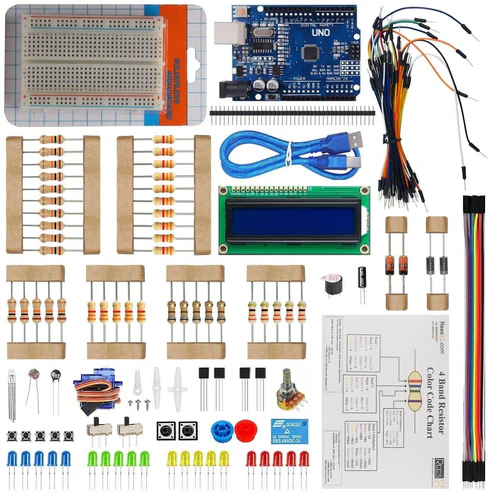
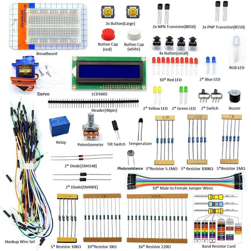
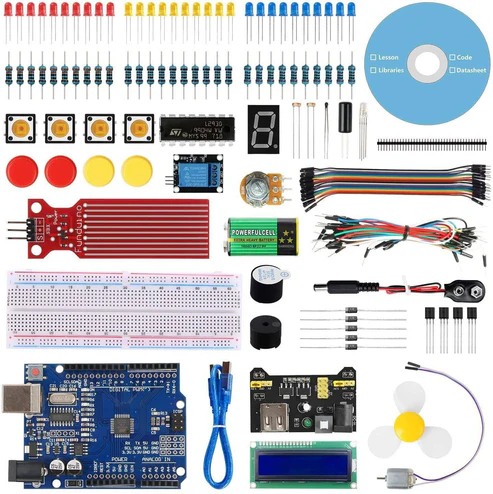
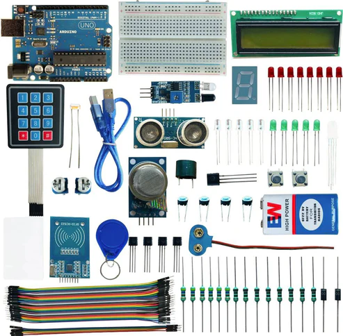
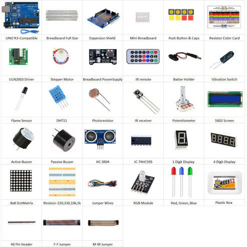
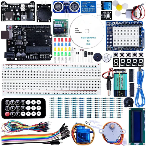
KIT CONTENT
Introduction
In this project we are making a home automation project in which we are using 2 channel relay modules using TTP223B touchpad Module interfacing with Arduino Uno. Here we will press the keys on touchpad to control the Relay 1 and Relay 2. If you are looking for applications like control AC lamp or High voltage DC device you need a relay, so let’s do something simple to control 2 channel relay modules.
HARDWARE REQUIRED
SOFTWARE REQUIRED
Arduino IDE 1.8.5 (programmable platform for Arduino)
Click To Download:https://www.arduino.cc/en/Main/Software


SPECIFICATIONS
TTP224B 4-CHANNEL CAPACITIVE TOUCH MODULE
- On-board TTP224 capacitive touch 4 key induction IC
- On-board 4 road level indicator.
- Working voltage: 2 V to 5.5 V DC
- Adjustable output mode, key output mode, longest time and fast/low power output
- PCB board size: 35(mm) x29 (mm).
ARDUINO NANO
| NANO |
| Microcontroller |
ATmega168 |
| Operating Voltage |
3.3V or 5V |
| Input Voltage |
3.35 -12 V (3.3V model) or 5 – 12 V (5V model) |
| Digital I/O Pins |
14 (of which 6 provide PWM output) |
| Analog Input Pins |
8 |
| DC Current per I/O Pin |
40 mA |
| Flash Memory |
16 KB (of which 2 KB used by bootloader) |
| SRAM |
1 KB |
| EEPROM |
512 bytes |
| Clock Speed |
8 MHz (3.3V model) or 16 MHz (5V model) |
2-channel 5V 10A relay Module
This is a 5V, 10A 2-Channel Relay interface board. It can be used to control various appliances, and other equipment’s with large current. It can be controlled directly with 3.3V or 5V logic signals from a microcontroller (Arduino, 8051, AVR, PIC, DSP, ARM, ARM, MSP430, TTL logic).
It has a 1×4 (2.54mm pitch) pin header for connecting power (5V and 0V), and for controlling the 2 relays. The pins are marked on the PCB:
- GND – Connect 0V to this pin.
- IN1 – Controls relay 1, active Low! The relay will turn on when this input goes below about 2.0V
- IN2 – Controls relay 2, active Low! The relay will turn on when this input goes below about 2.0V
- VCC – Connect 5V to this pin. Is used to power the optocouplers

PIN DESCRIPTION
TTP224B 4-CHANNEL CAPACITIVE TOUCH MODULE
VCC: 2V to 5.5V DC
GND: ground
OUT4: high/low output
OUT3: high/low output
OUT2: high/low output
OUT1: high/low output
ARDUINO NANO
| RAW |
For supplying a raw (regulated) voltage to the board |
| VCC |
The regulated 3.3 or 5 volt supply |
| GND |
Ground pins |
| RX |
Used to receive TTL serial data |
| TX |
Used to transmit TTL serial data |
| 2 and 3 |
Digital I/O pins. These pins can also be configured to trigger an interrupt on a low value, a rising or falling edge, or a change in value |
| 3, 5, 6, 9, 10, and 11 |
Digital I/O pins. They can also be configured to provide 8-bit PWM output |
| 10, 11, 12 and 13 |
Digital I/O pins. They can also be configured as SPI pins;
10 – (SS), 11 – (MOSI), 12 – (MISO) and 13 – (SCK) |
| A0 to A3 |
Analog input pins |
| A4 and A5. |
Analog input pins. They can also be used as IIC pins;
A4 – (SDA) and A5 – (SCL). |
| A6 and A7 |
Analog input pins |
| Reset |
The microcontroller can be reset by bringing this pin low |
2 channel 5v 10A relay Module
- COM– Common pin
- NC– Normally Closed, in which case NC is connected with COM when INT1 is set low and disconnected when INT1 is high;
- NO– Normally Open, in which case NO is disconnected with COM1 when INT1 is set low and connected when INT1 is high.
- Terminal 2 is similar to terminal 1, except that the control port is INT2
- INT 1– Relay 1 control port
- INT 2– Relay 2 control port


CIRCUIT CONNECTION
Connections are as follows :
- Out1 of TTP224 to the Nano D11
- Out2 of TTP224 to the Nano D10
- Out3 of TTP224 to the Nano D9
- Out4 of TTP224 to the Nano D8
- Ground to the negative rail and Vcc to the positive rail
- I2C module Vcc to positive rail and ground to the negative rail
- I2C module SDA pin to Nano A4 and SCL to A5 Nano
- Nano 5v pin to the positive rail
- IN1 of relay module goes to D4
- IN2 of relay module goes to D5
- Vcc of relay module to positive rail and ground to the negative rail


CODE
Click to see the code or copy the link:
https://drive.google.com/open?id=1zgu_BTbgCzaSqHQe0o0rDVSx10Y3XdPv
This sketch uses an ultrasonic rangefinder to determine the user’s gesture and outputs an IR signal to a sony TV based on the command given.
– High swipe (> 10in) = Channel Up
– Low swipe = Channel Down
– High hold (> 10in) = Volume Up
– Low hold = Volume Down
– Cover sensor (< 3in) = Turn On / Off
*/
#include <IRremote.h> // Library for IR Remote
// Defines for control functions
#define CONTROL_CH 1 // Channel change
#define CONTROL_VOL 2 // Volume
#define CONTROL_POW 3 // Power
#define CONTROL_UP 1
#define CONTROL_DOWN -1
#define DIST_MAX 20 // Maximum distance in inches, anything above is ignored.
#define DIST_DOWN 10 // Threshold for up/down commands. If higher, command is “up”. If
lower, “down”.
#define DIST_POW 3 // Threshold for power command, lower than = power on/off
// IR PIN
const int irPin = 3; // this is defined in the library, this var is just a reminder. CHANGING
THIS WILL NOT CHANGE PIN IN LIBRARY
// 2 Pin Ping Sensor
const int pingPin = 8; // Digital Pin 8 for Trigger Pin of Ultrasonic Sensor
const int echoPin = 7; // Digital Pin 7 for Echo Pin of Ultrasonic Sensor
// Confirmation LED Pins
const int led = 13; // internal LED for up/down debugging
const int ledR = 11; // Pin for Red
const int ledG = 10; // Pin for Green
const int ledB = 9; // Pin for Blue
// LED on timer
unsigned long timer;
// IR transmitter object
IRsend irsend;
// Power confirmation flag (needs two swipes to send signal)
boolean powerConfirmed = false;
/* The setup() function is called when a sketch starts. It is used to initialize variables, pin modes, start using libraries, etc. This function will only run once, after each power up or reset of the Arduino board. */
void setup()
{
// initialize serial communication and set pins
Serial.begin(9600); // Baud Rate
pinMode(led, OUTPUT); // LED acts as Output Pin
pinMode(ledR, OUTPUT); // LED (Red) acts as Output Pin
pinMode(ledG, OUTPUT); // LED (Green) acts as Output Pin
pinMode(ledB, OUTPUT); // LED (Blue) acts as Output Pin
pinMode(pingPin, OUTPUT); // Ping Pin acts as Output Pin
pinMode(echoPin, INPUT); // Echo Pin acts as Input Pin
timer = millis(); // Set timer to milliseconds
}
/* This Particular Function is used for Repeated Execution of the Circuit until Specified. */
void loop()
{
// Serial.println(millis());
long duration, inches;
int value; // Initialize variable
// Check for a reading
duration = doPing();
// Timer to confirm actions (currently only power)
if (timer && timer < (millis() – 5000) && (millis() > 5000))
{
Serial.println(“timer reset”); // Print the Message
timer = false; // Timer value
}
digitalWrite(led, LOW); // LED is inactive
setColor(0, 0, 0); // OFF condition
// convert the time into a distance
inches = microsecondsToInches(duration);
// If less than max inches away, act
if (inches < DIST_MAX)
{
// Debug output
Serial.print(inches);
Serial.println(“in”);
// If very close, it is a “power” signal
if (inches < DIST_POW)
{
Serial.println(timer);
// on or off
if (timer)
{
doIR(CONTROL_POW, 0);
timer = false;
delay(2000); // don’t want to be sending this more than once. 2 second delay
}
else
{
Serial.println(“power flag set”); // Print the Message
timer = millis();
setColor(255,50,50); // Set variations of RGB
delay(500); // Wait for 500 ms
}
}
else // is volume or channel
{
// Distance determines control direction
value = handleDist(inches);
// wait half a second
delay(300);
// check again, has hand disappeared?
if (microsecondsToInches(doPing()) > DIST_MAX)
{
doIR(CONTROL_CH, value); // swipe
}
else
{
// volume
int d = 500; // first delay is longer for single volume change
// repeat until hand is removed
while (inches < DIST_MAX)
{
value = handleDist(inches); // is up or down?
doIR(CONTROL_VOL, value); // fire off IR signal
delay(d); // wait
inches = microsecondsToInches(doPing()); // check for hand again
d = 100; // delays are shorter for quick multiple volume adjustment
}
delay(500); // this stops accidental channel change after volume adjustment
}
}
}
delay(50); // Short enough to detect all swipes.
}
/*
* If distance is within threshold, mark as ‘up’ and turn on corresponding LED.
*/
int handleDist(int inches)
{
if (inches > DIST_DOWN)
{
digitalWrite(led, HIGH); // LED is High
return CONTROL_UP;
}
else
{
digitalWrite(led, LOW); // LED is Low
return CONTROL_DOWN;
}
}
/*
* Fire off correct IR code
*/
void doIR(int control, int val)
{
switch(control)
{
case CONTROL_POW:
// power
Serial.println(“power on / off 0xa90”); // Print the Message
for (int i = 0; i < 3; i++)
{
setColor(255, 0, 0); // Set variations of RGB
irsend.sendSony(0xa90, 12); // Sony TV power code
delay(40);
}
break;
case CONTROL_CH:
setColor(0, 255, 0); // Set variations of RGB
// output ‘channel up / down’ depending on val
if (val == CONTROL_UP) // When both the values are equal
{
digitalWrite(led, HIGH); // LED is High
for (int i = 0; i < 3; i++)
{
irsend.sendSony(0x90, 12);
delay(40);
}
Serial.println(“channel up 0xD00A”); // Print the Message
}
Else // down
{
for (int i = 0; i < 3; i++)
{
irsend.sendSony(0x890, 12);
delay(40);
}
Serial.println(“channel down 0x3002”); // Print the Message
}
break;
case CONTROL_VOL:
setColor(0, 0, 255);
// output ‘volume up / down’ depending on val
if (val == CONTROL_UP) // When both the values are equal
{
digitalWrite(led, HIGH); // LED is High
for (int i = 0; i < 3; i++)
{
irsend.sendSony(0x490, 12);
delay(40);
}
Serial.println(“volume up 0x490”); // Print the Message
}
else //down
{
for (int i = 0; i < 3; i++)
{
irsend.sendSony(0xC90, 12);
delay(40);
}
Serial.println(“volume down 0xC90”); // Print the Message
}
break;
}
}
/*AnalogWrite uses pulse width modulation (PWM), turning a digital pin on and off very quickly
with different ratio between on and off, to create a fading effect. */
void setColor(int red, int green, int blue)
{
analogWrite(ledR, red); // Red is active
analogWrite(ledG, green); // Green is active
analogWrite(ledB, blue); // Blue is active
}
long doPing()
{
digitalWrite(pingPin, LOW);
delayMicroseconds(2);
digitalWrite(pingPin, HIGH);
delayMicroseconds(5);
digitalWrite(pingPin, LOW);
return pulseIn(echoPin, HIGH);
}
long microsecondsToInches(long microseconds)
{
// According to Parallax’s datasheet for the PING))), there are
// 73.746 microseconds per inch (i.e. sound travels at 1130 feet per
// second). This gives the distance travelled by the ping, outbound
// and return, so we divide by 2 to get the distance of the obstacle.
return microseconds / 74 / 2;
}
long microsecondsToCentimeters(long microseconds)
{
// The speed of sound is 340 m/s or 29 microseconds per centimeter.
// The ping travels out and back, so to find the distance of the
// object we take half of the distance travelled.
return microseconds / 29 / 2;
}
WORKING
Upload the code and see the output.
If you are looking for applications like control AC lamp or High voltage DC device you need a relay, so let’s do something simple to control Relay 2 channel
Touch Pad 1 and 2 to control Relay #1
Touch Pad 3 and 4 to control Relay #2